


EMI/RFI control is one of those engineering disciplines that almost never gets celebrated, even though it decides whether modern technology actually works. The best shielding and grounding strategies don’t draw attention to themselves. They quietly keep a system stable when switching edges sharpen, component density increases, and the outside world turns into an increasingly noisy electromagnetic environment.
What’s changed in the last decade isn’t the underlying physics. Maxwell didn’t update his equations for Wi-Fi 7, quantum computing, or grid-scale battery storage. What’s changed is the way technologies are converging. Systems that used to be separate—power conversion, high-speed digital compute, sensing, wireless links, and thermal management—now live in tight proximity. That makes EMI/RFI less like a compliance checkbox and more like a cross-disciplinary reliability problem.
And that’s why the same EMI/RFI questions show up in two places that could not feel more different: a cryogenic quantum lab and a renewable energy installation built for megawatts.

Quantum environments: when the system is too sensitive for the real world
Quantum systems force engineers to treat “noise” as a first-order design constraint. In many quantum and quantum-adjacent setups, the signals are so small and the operating states so delicate that what looks like minor interference in other electronics becomes a genuine performance limiter. In this world, EMI/RFI doesn’t just cause occasional glitches; it can erode coherence and stability—the very traits quantum platforms depend on.
The interference isn’t only coming from obvious sources. It can couple in through facility infrastructure, nearby lab equipment, cable routing, grounding inconsistencies, and enclosure seams. The difficulty is that once interference enters the system, it tends to be difficult to localize. It finds paths you didn’t “design” but inadvertently created: along a shield seam, through a connector interface, across a gap that becomes an antenna at the wrong frequency.
This is where the practical, physical details matter. A shield is not simply a material choice; it’s a geometric object with edges, seams, and interfaces. If that interface isn’t electrically continuous, the shield behaves more like a suggestion than a barrier.

In real builds, effective EMI/RFI protection in sensitive environments usually combines multiple layers of control:
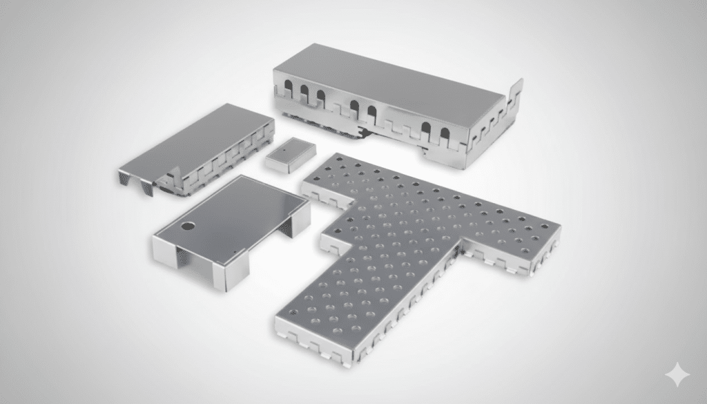
- At the PCB level, Board Level Shields help isolate aggressive components and reduce coupling into neighboring circuitry.
- At the enclosure level, conductive elastomer gaskets can maintain electrical continuity while tolerating mechanical variation, thermal cycling, and service access.
- Where consistent compression and mechanical compliance are needed, fabric-over-foam gaskets help maintain contact along removable panels and lids.
- For access doors or panels that must open and close frequently, beryllium copper (BeCu) fingerstock gaskets provide durable, low-resistance grounding while maintaining excellent EMI/RFI shielding performance across repeated mechanical cycles.
Those aren’t redundant. They do different jobs at different scales. The point is that EMI/RFI control in a quantum setting often demands a “defense in depth” approach—not because we love complexity, but because sensitivity leaves little margin.
Another piece that tends to be underestimated is contact integrity. In a high-sensitivity environment, the difference between a good design and an intermittently failing design can be something as simple as inconsistent grounding contact across assemblies. Spring contacts and stamped contacts can provide reliable, repeatable electrical contact between shielding elements and grounded structures, particularly where vibration, thermal cycling, or assembly tolerances would otherwise introduce variability. It’s not glamorous, but it’s the kind of detail that prevents a shielding strategy from degrading into a collection of loosely-related metal parts.
Finally, thermal stability is not separate from EMI/RFI in these environments. Temperature changes can shift electrical behavior; electrical behavior can shift noise; noise can shift system stability. That feedback loop is why thermal interface materials often belong in the same design conversation as shielding and grounding. In advanced electronics, including quantum-adjacent control and readout systems, thermal design is frequently one of the quiet enablers of electromagnetic stability.

Renewable energy systems: when the system is powerful enough to be its own source of interference
Renewable energy installations flip the problem. Instead of asking how to protect an ultra-sensitive system from a noisy world, the system itself is often the primary noise generator.
Modern inverters, converters, and battery systems depend on high-speed switching. Fast edges improve efficiency, reduce losses, and enable smaller magnetics—but they also produce broad spectral content that can become EMI/RFI through radiation, conduction, or both. In practice, engineers end up balancing electrical performance against electromagnetic containment and thermal constraints.
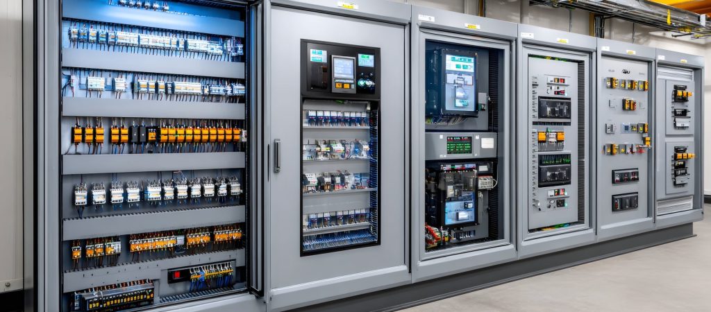
The enclosure matters more than it gets credit for. Power electronics enclosures aren’t just boxes; they’re part of the electromagnetic system. Any seams, access panels, ventilation openings, or connector cutouts can become leakage points. At the same time, those enclosures must dissipate heat and survive outdoor environments. This is where conductive elastomers, fabric-over-foam gaskets, and beryllium copper (BeCu) fingerstock play complementary roles.


Conductive elastomers provide durable EMI/RFI sealing while tolerating environmental exposure. Fabric-over-foam materials maintain consistent compression across removable panels and lids, helping preserve shielding integrity over time. BeCu fingerstock gaskets, often used along enclosure doors and high-cycle access points, provide reliable grounding and low-resistance contact while maintaining strong shielding performance through repeated opening and closing.
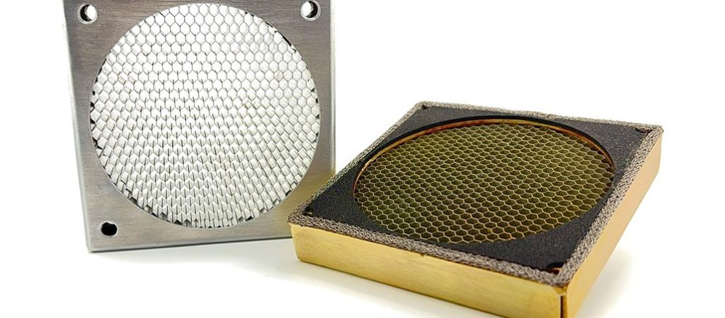
Ventilation is one of the classic friction points: you need airflow, but openings compromise shielding. Shielded vent panels exist for exactly this reason—allowing airflow while preserving EMI/RFI attenuation. In renewable systems, that’s not an academic concern. It’s the difference between an enclosure that behaves as intended and one that becomes an antenna farm.
Cables are the other major story. Long cable runs are unavoidable in renewable installations. Unfortunately, long cables are also excellent antennas, and switching noise loves to travel along conductors. That’s why suppression at the cable level often matters as much as enclosure shielding. Ferrite cable shielding components are a practical tool for reducing high-frequency noise traveling along cables, helping limit both conducted and radiated emissions. They’re not always the headline item in an EMI/RFI discussion—but in power conversion environments, they’re frequently one of the most cost-effective levers available.
And again, thermal cannot be separated. Heat increases resistance and can change switching behavior; changes in switching behavior change emission profiles. As wide-bandgap semiconductors become more common, the combination of higher switching speeds and higher power density makes thermal interface strategy even more critical. Thermal interface materials—often discussed as a cooling topic—end up functioning as reliability infrastructure for EMI/RFI consistency.
The real issue: convergence forces disciplines into the same enclosure
The most interesting part of the “quantum to renewables” comparison is that it exposes a broader shift: EMI/RFI control is no longer isolated to a single domain. Modern systems combine power conversion, high-speed digital processing, sensing, and wireless communication in tight spaces.
That convergence shows up everywhere. Data centers pack high-speed compute next to dense power conversion. Medical electronics require signal integrity and compliance in electromagnetically crowded environments. Aerospace systems demand shielding continuity under vibration and extreme conditions. In each case, the same EMI/RFI mechanics apply—fields couple, seams leak, cables radiate, grounding paths matter—but the constraints vary.
To make that tangible, here’s a short example of how the same interference mechanism behaves differently depending on context:
- In a quantum-adjacent system, a small leakage path might manifest as degraded measurement fidelity.
- In a renewable inverter, a similar leakage path might manifest as a compliance failure, malfunctioning sensors, or interference with nearby equipment.
- In a communications-heavy system, it might manifest as reduced link margin, higher error rates, or intermittent performance issues that look like “software bugs” until they don’t.
That’s why EMI/RFI control is increasingly a systems engineering discipline. It’s not just an electrical problem. It’s mechanical design, materials science, thermal behavior, assembly tolerance, and lifecycle reliability.
Mechanical precision is electromagnetic performance
At high frequencies, geometry becomes electrical. A seam gap that looks trivial in CAD can become meaningful at the wrong wavelength. A gasket that “sort of” touches can behave very differently across temperature cycles or after repeated service access. A contact surface that oxidizes or loses compression can increase resistance and break the continuity that shielding depends on.
This is the quiet importance of precision metal fabrication design, and precision forming in EMI/RFI design. The repeatability of a formed shield, the consistency of mating surfaces, the proper selection of materials and platings for Galvanic Compatibility, and the reliability of contact points can determine whether the design performs consistently across production. When designs move from prototype to volume, these “manufacturing details” become the electromagnetic reality.
It also explains why spring contacts and stamped contacts deserve more attention than they typically get. In many real assemblies, they are what converts a theoretical shielding concept into a mechanically tolerant, repeatable electrical interface—especially where you need predictable grounding without relying on perfect alignment every time.
Why “fixing it later” usually costs more
EMI/RFI is notorious for appearing late, after mechanical layouts are locked and PCB revisions feel expensive. But treating EMI/RFI as a late-stage correction tends to produce the most painful outcomes: rushed retrofits, bulky add-ons, unpredictable results, and unnecessary redesign loops.
Designing early doesn’t mean overengineering everything. It means making sure EMI/RFI has a seat at the table when the big decisions happen: enclosure design, grounding architecture, ventilation strategy, cable routing, and PCB partitioning. The earlier those fundamentals are set, the more likely it is that shielding elements—Board Level Shields, conductive gasketing, vent panels, ferrite components, and robust grounding contacts—function as integrated parts of the system rather than emergency patches.
One physics problem, many engineering cultures
From quantum labs to renewable energy systems, the same truth holds: EMI/RFI is not an industry-specific nuisance. It’s a universal constraint that shows up wherever electronics get faster, denser, and more integrated.
The difference between these worlds isn’t the physics; it’s the tolerance. Quantum systems can’t tolerate much noise. Renewable power systems generate a lot of noise. The shared challenge is controlling the electromagnetic environment so the system behaves predictably over time—through thermal swings, mechanical stress, service events, and real-world variability.
That’s why EMI/RFI control is inherently cross-disciplinary now. It lives in the overlap between materials and mechanics, thermal performance and electrical integrity, manufacturing repeatability and field reliability. When done well, it doesn’t call attention to itself. It just allows modern technology—whether it’s an experimental quantum platform or a renewable energy converter—to perform as designed.