

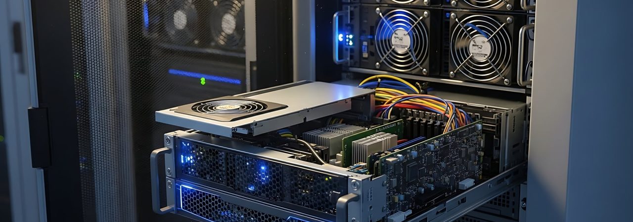
Fans and vents are essential in many electronic enclosures, but the opening that releases heat can also become one of the weakest points in the enclosure’s electromagnetic boundary.
This challenge appears in server and telecommunications chassis, power supplies, industrial control cabinets, RF equipment, defense electronics, and other systems that depend on forced-air cooling. Processors, switching power circuits, communication modules, and high-speed digital electronics generate heat while also producing electromagnetic energy across a wide range of frequencies.
An unrestricted fan cutout may support cooling but provide a direct path through the enclosure wall. A more restrictive ventilation structure may reduce electromagnetic leakage but change the fan’s operating point and the volume of air delivered to internal components.
The solution involves more than selecting a vent with an acceptable airflow rating. Engineers must consider opening geometry, operating frequency, pressure drop, fan location, internal layout, perimeter contact, enclosure seams, cable paths, environmental exposure, and maintenance requirements as parts of the same assembly.
Design Brief
A fan-cooled enclosure must move sufficient air through the system without allowing the ventilation opening to become a dominant electromagnetic leakage path. The design must account for vent dimensions, honeycomb cell geometry, frequency, pressure drop, fan performance, source location, mounting continuity, environmental exposure, and service access. Depending on the conditions, the enclosure may require vented panels, conductive gaskets, resilient contacts, conductive foam, or ferrite cable shielding at different locations.
Inside a Fan-Cooled Electronic Enclosure
A ventilated enclosure may contain:
- Processors and high-speed digital circuits
- Switching power supplies and converters
- RF and communication modules
- Fans and fan-control electronics
- Heat sinks and power devices
- Internal power and signal cables
- Input/output connectors
- Removable fan trays or power modules
- Access panels, filters, guards, and vents
- Electronic racks with fans
Each feature affects the movement of heat, electromagnetic energy, or both.

Circuit boards, cable bundles, card guides, and heat sinks shape the internal airflow path. Air may bypass a hot component, recirculate through an open space, or encounter more resistance than expected. Filters and guards introduce additional restrictions that may not be represented by the fan’s free-air rating.
Electromagnetic energy also follows several paths. It may couple directly between nearby circuits, travel along power or signal conductors, or escape through vents, seams, connectors, and removable panels. Internal cables can carry noise from a switching circuit toward an opening located elsewhere in the enclosure.
These interactions make the final assembly more important than any isolated component specification. Vent dimensions, fan position, component layout, grounding, panel construction, and enclosure interfaces all influence performance.

How Openings Change the Electromagnetic Boundary
A conductive enclosure helps control radiated interference by creating a continuous electrical boundary around the electronics. Every ventilation opening interrupts that boundary.
The significance of an opening depends on its individual dimensions, depth, shape, orientation, and relationship to the frequencies of concern. Total open area matters for cooling, but it does not fully describe electromagnetic behavior.
A single large fan cutout creates a more direct path through the enclosure wall than a structure that divides the same area into many smaller conductive passages. This is the operating principle behind honeycomb-style EMI vent panels.
The honeycomb structure creates a conductive barrier that attenuates electromagnetic signals while maintaining open airflow paths. When its dimensions are appropriately related to the frequencies being controlled, electromagnetic energy is attenuated as it travels through the cell. Cell depth also matters: a longer passage can provide more attenuation than a shallow opening with the same cross-sectional dimensions.
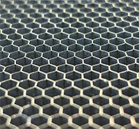
These relationships create practical tradeoffs. Smaller cells and greater depth can support stronger shielding performance, but they may increase airflow resistance, panel thickness, weight, or cost. Larger cells and shallower construction can reduce resistance but may provide less attenuation at relevant frequencies.
Vent location adds another variable. A panel installed near a switching power supply, processor, fan controller, or cable bundle may be exposed to stronger electromagnetic fields than an identical panel positioned elsewhere. The vent should therefore be evaluated in relation to the internal sources, not only as an opening in an otherwise empty enclosure.
Systems Most Affected by Ventilation Decisions
Power Supplies and Power Electronics
Switching power supplies, converters, and motor drives can produce substantial heat and broadband electrical noise. Locating them near an exhaust may improve heat removal, but it also places a strong noise source close to the enclosure opening.
Their input, output, and control conductors may carry high-frequency common-mode noise toward other parts of the system. Ferrite cable-shielding components can be considered where testing identifies the cable as a significant conducted or radiated path.
Processors and High-Speed Digital Circuits
Processors, memory, clocks, and high-speed interfaces generate harmonics that can extend far beyond their fundamental operating frequencies. These components often require direct airflow or heat sinks, making their physical relationship to the inlet or exhaust important.
A processor located immediately behind a vent may experience effective cooling while also producing stronger emissions at the opening. Internal spacing, orientation, shielding structures, and vent placement may need to be adjusted together.


RF and Communication Modules
Communication and receiver circuits may be affected by external energy entering the enclosure or by noise generated elsewhere inside it. Vent orientation, internal partitions, nearby cables, and distance from the panel can influence coupling into these modules.
Fans and Fan-Control Electronics
Fan motors, commutation, control wiring, and pulse-width-modulated speed controls can introduce noise near the ventilation opening. That noise may travel along the fan leads or couple into nearby circuitry.
A ferrite placed on the fan or control cable may help when cable-borne high-frequency noise is confirmed, but it does not replace a shielded vent or correct a poor enclosure interface. It addresses a different path within the same system.
Removable Modules and Service Panels
Fan trays, power-supply modules, filter housings, and access panels introduce seams around the ventilation system. Their shielding interfaces may be opened repeatedly, exposed to abrasion, or limited by closure force. Those mechanical conditions influence whether a foam gasket, elastomer, knitted-wire gasket, or spring contact is appropriate.
Design Detail
A larger vent may reduce airflow resistance but create a larger electromagnetic interface. A deeper honeycomb core or smaller cell geometry may improve attenuation while increasing pressure drop or installation depth. Vent size, cell geometry, fan performance, operating frequency, and available enclosure space should therefore be evaluated together.

Vent area can be increased to reduce face velocity and pressure drop, but available panel space may be limited. A higher-speed fan may recover airflow but increase acoustic noise, power consumption, and wear. A deeper honeycomb core may support greater attenuation while introducing additional airflow resistance and mechanical depth.
Thermal testing should include the actual vent, filter, guard, fan arrangement, and internal hardware. Testing with an unrestricted opening and installing the EMI vent afterward may produce temperature results that do not represent the finished system.
Building a Reliable Interface Around the Vent
The honeycomb core cannot support enclosure-level shielding if energy can pass around the vent frame. Paint, powder coating, oxidation, contamination, uneven flanges, widely spaced fasteners, and distorted sheet metal can all interrupt contact between the frame and enclosure.
Conductive plating lowers surface and contact resistance, helping the vent frame maintain electrical continuity with the enclosure and limiting EMI leakage around the opening. Because plating options differ in conductivity, material compatibility, and long-term electrical performance, the appropriate finish depends on the enclosure material, vent location, and required shielding effectiveness.
Selecting the appropriate plating helps establish a conductive surface around the vent, but the finish alone cannot bridge gaps or maintain contact across every enclosure joint. Gaskets and other conductive contact products are therefore selected according to the mechanical demands of each interface.

Fabric-Over-Foam Shielding Gaskets provide low compression force and conformability for lightweight vent frames, access panels, and covers. Multiple profiles allow the gasket shape to be matched to the available flange and compression direction.
Conductive Elastomers may be more appropriate where the joint must withstand moisture, chemicals, temperature changes, or other demanding environmental conditions. Extruded profiles, molded parts, sheet materials, and die-cut configurations provide options for different mounting geometries.
Beryllium Copper Fingerstock provides spring contact for fan trays, filter housings, doors, removable modules, and other interfaces that may be opened frequently. Its resilience makes it useful where repeated cycling and reliable grounding contact are important.
TechMESH Knitted Wire Gaskets can support mechanically demanding enclosure joints. All-mesh constructions provide conductive knitted-wire contact, while elastomer-core and combo constructions add resilience and allow the contact behavior to be matched more closely to the joint.
Conductive Foam Shielding offers a lightweight, conformable option for delicate panels, narrow flanges, I/O areas, and space-constrained interfaces where low closure force is important.
Ferrite Cable Shielding adds impedance to high-frequency common-mode noise on power, signal, and control cables when wiring becomes a conducted or radiated interference path.

These products are not interchangeable. Compression range, flange width, surface finish, abrasion, vibration, temperature, corrosion, environmental exposure, and maintenance frequency should determine the selection.
Controlling the Paths Beyond the Vent Opening
Correcting the strongest leakage path may not bring the enclosure to its required performance if several other paths contribute at similar levels. Once the dominant path is reduced, another opening or interface may become the new limiting factor.
The result should be measured after each change and compared across the relevant frequency range. One modification may reduce emissions at certain frequencies while leaving others largely unchanged, indicating that more than one coupling path is involved.
A combined approach is appropriate only when testing confirms multiple contributors. The objective is to address each verified path in sequence, not to add shielding products throughout the enclosure without evidence that they are needed.
Matching the Solution to the Enclosure
| Enclosure location or condition | Primary requirement | Potential Leader Tech solution |
|---|---|---|
| Large square or rectangular ventilation opening | Combine substantial airflow area with honeycomb EMI attenuation | 9100 Series Tech Vent Panels |
| Fan-mounted circular opening | Fit standard fan arrangements with a compact circular honeycomb panel | 9700 Series Tech Vent Panels |
| Lightweight vent frame or removable cover | Maintain continuity with low compression force | Fabric-Over-Foam Shielding Gaskets |
| Outdoor, chemically exposed, or environmentally demanding joint | Combine conductive contact with environmental resistance | Conductive Elastomers |
| Frequently removed fan tray, filter housing, or service door | Maintain resilient contact through repeated opening cycles | Beryllium Copper Fingerstock |
| Rugged enclosure joint exposed to demanding operating conditions | Support demanding mechanical interfaces with multiple construction options | TechMESH Knitted Wire Gaskets |
| Narrow flange, delicate panel, or restricted space | Provide conformable contact with low mechanical force | Conductive Foam Shielding |
| Fan leads or control cables carrying high-frequency noise | Add impedance to a confirmed cable-borne interference path | Ferrite Cable Shielding |
These are possible starting points rather than universal prescriptions. Product selection should follow the identified source, coupling path, frequency range, airflow requirement, mechanical design, and operating environment.
Where Leader Tech Fits in the Design
Leader Tech currently offers two Tech Vent configurations for different enclosure geometries.
The 9100 Series provides framed aluminum honeycomb panels in square and rectangular dimensions for larger ventilation areas. These panels are applicable to server, telecommunications, industrial, power, RF, aerospace, and defense enclosures that require substantial inlet or exhaust area.
The 9700 Series uses a compact circular configuration designed around common fan sizes. It is suited to applications where the shielded ventilation panel must align directly with an individual fan opening.
Both series are available with material and finishing options that allow the panel construction to be evaluated for shielding requirements, corrosion resistance, galvanic compatibility, and environmental durability.
Around the vent and elsewhere in the enclosure, our product range provides several ways to maintain conductive continuity. Fabric-Over-Foam and Conductive Foam support low-force interfaces. Conductive Elastomers address joints with more demanding environmental requirements. BeCu Fingerstock supports repeatedly accessed assemblies. TechMESH provides knitted-wire options for robust enclosure contacts. Ferrite cable-shielding components can address high-frequency noise on fan, power, or control wiring when the cable is part of the coupling path.
The appropriate combination depends on the completed assembly. Airflow targets, pressure-drop limits, frequencies of concern, flange geometry, surface condition, compression, service access, and environmental exposure should be established before the vent and surrounding interfaces are finalized.
Frequently Asked Questions
What is the difference between the 9100 and 9700 Series Tech Vents?
The 9100 Series includes square and rectangular framed honeycomb panels for larger ventilation openings. The 9700 Series uses a compact circular design matched to common fan sizes for direct fan-mounted applications.
How does a honeycomb vent control electromagnetic leakage?
The honeycomb divides a large opening into many smaller conductive passages. Electromagnetic energy is attenuated as it travels through those passages, while air remains able to move through the cells.
Why is pressure drop important when selecting a Tech Vent?
Pressure drop affects the fan’s operating point and the amount of air moved through the enclosure. The vent must be evaluated together with filters, guards, heat sinks, internal obstructions, and the fan performance curve.
How should engineers choose between the available gasket and contact products?
The selection depends on compression force, flange space, environmental exposure, abrasion, vibration, temperature, and service frequency. Fabric-Over-Foam and Conductive Foam suit low-force interfaces; Conductive Elastomers support demanding environments; Fingerstock supports repeated access; and TechMESH provides durable knitted-wire constructions.
When should ferrite cable shielding be considered?
Ferrites may be appropriate when testing identifies high-frequency noise traveling along fan, power, signal, or control wiring. The ferrite must be matched to the frequency range, conductor arrangement, and current conditions.
Designing the Complete Airflow Interface
Cooling and EMI/RFI shielding share the same enclosure space but depend on different physical conditions. Effective ventilation requires enough open area and fan capacity to remove heat, while effective shielding requires those openings and surrounding joints to remain electrically controlled.
Optimizing either requirement independently can create problems elsewhere. A less restrictive opening may improve airflow but reduce shielding performance, while a more aggressive vent configuration may increase pressure drop and leave internal components operating at higher temperatures.
The final design must account for how the fan, vent, filters, enclosure interfaces, and internal layout perform together. This means evaluating cooling under realistic airflow resistance and confirming EMI/RFI performance with the vent fully mounted in the finished enclosure.
The goal is balance—not compromise.